


Tripod Restoration-The Start
Step into the world of gears, brass, and Victorian ingenuity with this beautifully restored antique camera tripod—reimagined in full steampunk style. In this post, watch as a forgotten relic is transformed into a stunning functional art piece, blending industrial aesthetics with old-world craftsmanship.
From intricate metal detailing and weathered wood restoration to custom brass fittings and mechanical accents, every step of the process highlights the artistry behind steampunk design. Whether you’re a fan of vintage photography, DIY restoration, or retro-futuristic creations, this project offers both inspiration and insight.
Perfect for collectors, makers, and anyone who appreciates the fusion of history and imagination.
Last year, I finished working on an antique camera. It fit well with the Steampunk theme of my website. All that was needed was someplace to mount the camera, while maintaining the Steampunk theme.


I purchased this tripod a number o f years ago at a local flea market. When I bought it I knew that I liked the Steampunk look of the piece. It languished in my workshop for a number of years. Then last year I completed the camera and realized I had the perfect piece to make it complete.

One of the things I really liked about it was the crank mechanism for raising and lowering the camera. It gives the tripod that steampunk flair and makes it stand out from modern designs.
Some Background

The tripod design was patented in 1926 by Theodore A Jansson. In this diagram taken from the patent you can see the style of the design.


For those who are interested I attached a copy of the entire patent above.

The patent number was stamped into the wood of the camera mount as well as one of the legs. The patent shows it was originally invented in 1926. However, I don’t know the exact age of this particular tripod. I think this design was used for at least several decades. My guess is the 1030’s or 1940’s. Based on the stamp, the tripod was manufactured by Ansco out of Binghampton New York. This company was a photography supplier that operated as ANSCO from 1901 until the mid 1980’s.


These are some closeups of the initial state of the tripod. You can see the other information stamp in the top section of one of the legs. The tripod has mostly just dirty though it has also seen some wear and tear. Some of the wood is cracked with delaminations present in some of the plywood pieces. Several of the mechanical pieces will need some repairs as well.
Let’s Take it Apart


The next step is taking the tripod apart. As the pieces are removed I place them in zip lock bags, each labeled with what area/part they came from.


These are some closeups of the tripod as various parts were removed. A closeup of the crank mechanism is seen on the left.


Each leg of the tripod is made of three pieces of wood. Two outside sticks on each side of central stick that can be extended. Metal clamps on each leg can be tightened to hold the leg length in place.

You can see here that the knobs on the leg clamps have become mismatched over the years. They fit over a 1/4 inch brass shaft and are held in place with a set screw. The 1/4 inch shaft is pretty common for off the shelf knobs like this so finding replacements shouldn’t be hard. I plan to replace these with knobs that match each other as well as the tripod theme.


The central mast has a metal rack attached that is utilized for raising and lowering it inside the tripod via a hand crank. There is also a brass strip along one edge that serves as a contact point for set-bolts that hold the camera mast in place once the desired height is achieved.
Some Gluing is Needed


The mast is cracked on the top end. Here I am working glue into the crack. Then, I apply clamps to hold it in place while the glue sets.


The camera holder back has two problems. The felt that was originally applied to the surface has deteriorated. I remove this with various scarping tools, water and knives. This reveals the second problem, a crack running along the center. This I glue and clamp in place.

Both plywood pieces of the camera mount had delaminations. I worked glue was into the gaps then clamped them while they dried.


One of plywood layers had a small section of the top layer missing. In order to repair this I make and shape a filler piece from oak and glue it in place.


After the glue dries I use small files and sand paper to shape the filler piece. I then use dark stain to color the completed repair.
And Some Cleaning


The camera mount rotates on top of the central shaft. This metal disk mounts to the central mast. It allows the camera mount to swivel. This just needs some cleaning and sanding.


After I have completed the repairs and cleaning, I put the camera mount back together.
Starting to Take Shape


I reattach the rack and the cleaned brass strip to the central shaft. In the picture on the right I attach the repaired camera mount to the swivel. You can see that the cleaned rack has also been attached.


I use green adhesive felt to replace the rotted material that I scraped off the camera mount.
Cleaning Things Up


I use some 409 cleaner to remove the grime from the crank, clamps and fastener pieces.


I also use 409 to clean all of the dirt from the wood surfaces of the legs. After cleaning I use “Old English” wood cleaner and preservative to treat the wood. After cleaning, car wax was used to coat the surface of the metal pieces as well.
Fixing Some Threads


The leg extension clamps have messed up threads where the 1/4 inch shafts screw into brass square pieces . For the square brass bases I am able to use a die to clean up the threads. In the case of the brass posts, I use brass rod to make replacement parts.


The base tripod piece just needs some cleaning. I don’t separate the legs from the braces or central support. These are held in place by rivets and I feel I’ll do more damage if I try to take them apart.
Crank Mount.


The mounting shaft for the hand crank is seen here on the right. When I removed this from tripod I didn’t realize there was a metal pin holding it in place. This was to prevent the shaft from loosening during use, but it caused some damage to the threads. After cleaning up the threads on both pieces everything worked perfectly.


Rather than using a metal pin to hold the shaft in place, I opted to drill and tap the hole from the old pin and added a set screw. This holds the shaft in place and can be removed easily for repairs. The original pin had been driven in, then sanded and painted over. The set screw will be more obvious for future users.
Let’s Put it Together


With the clamps and hardware cleaned up and repaired, I put the tripod completely back together.
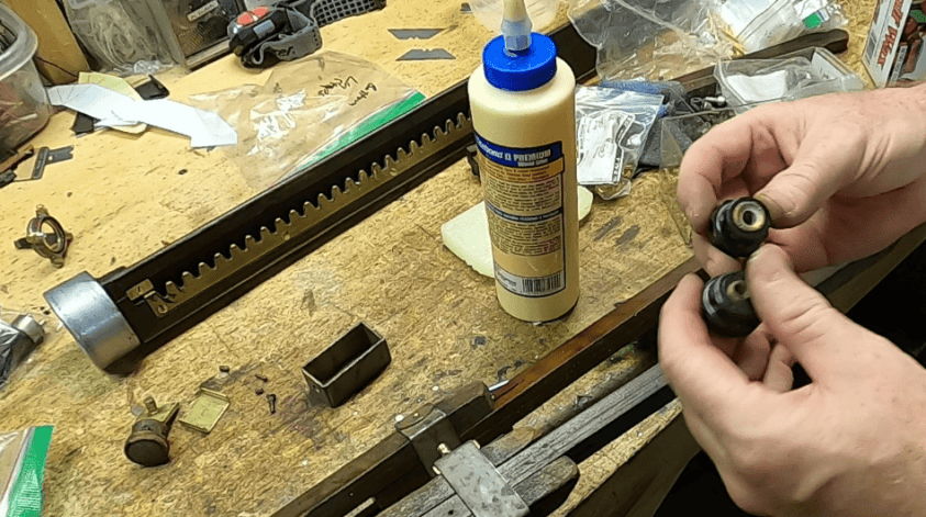


I was able to find three of these matching knobs in my collection that fit the design perfectly and used them to replace the assorted originals.


The tripod is looking pretty good. It is now clean and all pieces are functioning. There is, however, one small problem I found when I got things back together.
A New Locking Bolt


This knob attached to a threaded brass shaft is used to clamp the main camera mast in place. You would adjust the height of the mast using the hand crank, then lock it in place with the two brass bolt knobs, one on the bottom and this one at the top. The top locking bolt has two problems. The threads of the brass screw are damaged from applying too much force while tightening. The screw is also to short to adequately secure the mast in place. I don’t know if this is due to a break, ware and tare or just being poorly made. In any case I decide to make a new screw/shaft piece from brass stock. I first remove the threaded section from the knob. This way I can size up what I need to do next.


Then I cut a piece of 1/4 inch brass rod to length on the lathe. Next I turn the shaft to the right diameter. After that, I use a 1/4 inch 20 TPI die to thread the shaft.


I add a little divot to the top section of the shaft. This allows the set screw on the knob to rest in it. I use the mill to get an accurate placement. You can see here that the new shaft is about a 1/2 inch longer than the old one. Now I can put the knob onto the new locking bolt and it’s ready to go.


With the knew threaded brass rod in place the locking bolt now holds the mast in place after adjusting the height as it should.
How it works


By loosening the bolt the crank can now raise and lower the camera that would be mounted the base at the top of the mast. The image on the left is the top bolt just replaced and the image in the center is the bottom bolt. Both are loosened to adjust the mast height, then tightened when the desired heaght is achieved.


One knob under the base secures the tilt angle of the camera base.


The the tightens and loosened the swivel.


The tripod itself is now complete. Here are two images of the camera mount. The one on the left is with the mount folded. On the right the mount is open. For the actual cameras this tripod was designed for the camera would have been bolted to the mount with the back against the felt. My camera will need to be mounted differently.
Mounting the Camera

To mount the Dropping Plate Camera I restored in a previous blog post to this tripod, I’ll need to make some brackets. I am using these brass pieces from my antique clock parts drawer. The idea is to create two plates. One will be in front of the camera, and the other will be behind it. These plates will hold the camera in place by clamping the camera between them.

I want to use the two bolts that come through from the under/back side side of the felt. These have Bakelite knobs on the other end are used to mount a camera to the felt side of the base. To hold my camera I will use the brass nuts I added to these bolts. My plan is to use some brass clock chassis scrap pieces to form L-brackets that will hold the camera to the felt surface vertically.
Shaping Some Brackets- Rear


For the rear bracket I used this brass plate from my antique clock parts bin. First, I had to cut a section off of the plate that I didn’t need. Then the two metal shafts protruding from it were removed. Then a center hole was drilled. The hole is for mounting to the base with the bolts and nuts seen above.


With the posts out of the way I can bend the bracket into shape. In the last image the front bracket is ready for the next step.
The Front Bracket
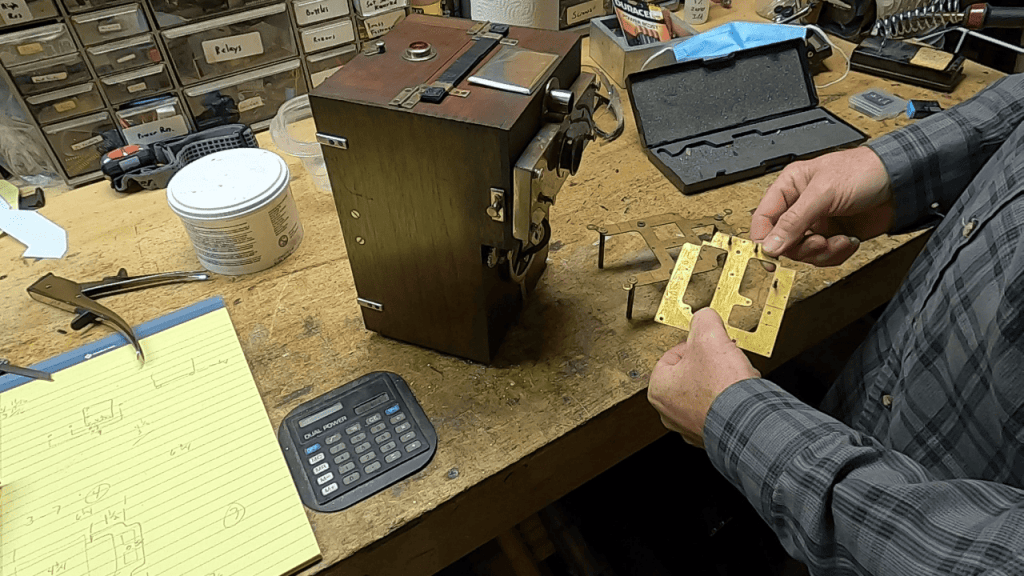
The rear bracket is going to be made from this more obtuse piece.

After cutting we are left with the bracket cut to about the right shape.


Next, I mark and round the “ears” of the bracket so it will match the those on the rear bracket.


This bracket was is then cleaned up with a file , drilled and finally bent into an L shape.


The brackets are now close to being done.


As a final element I am using some brown adhesive rubber bumpers for the camera contact surfaces of the brackets. These allow me to squeeze the camera between the front and back brackets. This holds the camera securely without damaging the it.
Connecting to the Camera


The back bolt on the camera platform is mounted in a slot. This makes it possible to slide the back bracket against the camera forcing it against the front bracket. This holds the camera in place.


The Antique Dropping Plate Camera mounted to the Steampunk Tripod is now complete. With that the whole piece can take pride of place as part of my Steampunk Livingroom.